Measurement of Capacitance By Schering Bridge:
We will discuss the measurement of capacitance by Schering bridge.The connection and phasor diagram of Schering Bridge under balance conditions are shown in the below figure.
Let
C1 = capacitor whose capacitance is to be determined,
r1 = a series resistance representing the loss in the capacitor
C2 = a standard capacitor.This capacitor is either an air or a gas capacitor and hence is loss-free.However, if necessary, a correction may be made for the loss angle of this capacitor,
R3 = a non-inductive resistance,
C4 = a variable capacitor, and
R4 = a variable non-inductive resistance in parallel with variable capacitor C4.
Must Read:
Must Read:
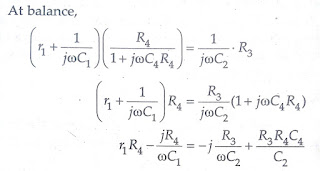
Equating the real and imaginary terms, we obtain
r1 = R3C4/C2
and C1 = C2 ( R4/R3)
Two independent balance equations are obtained if C4 and R4 are chosen as the variable elements.
Must Read:
Must Read:
Measurement of dissipation factor by Schering Bridge:
Dissipation factor,
D1 = tan δ = ωC1r1 =ω(C2R4/R3) x (R3C4/C2) = ωC4R4
Therefore values of capacitance C1, and its dissipation factor are obtained from the values of bridge elements at balance.
Permanently set up Schering bridges are sometimes arranged so that balancing is done by adjustment of R2 and C4 with C2 and R4 remaining fixed. Since R3 appears in both the balance equations and therefore there is some difficulty in obtaining balance but Schering Bridge has certain advantages as explained below :
The equation for capacitance is C1 = (R4/R3) C2 and since R4 and C2 are fixed, the dial of resistor R3 may be calibrated to read the capacitance directly.
Dissipation factor D1 = ωC4R4 and in case the frequency is fixed the dial of capacitor C4 can be calibrated to read the dissipation factor directly.
Let us say that the working frequency is 50 Hz and the value of R4 is kept fixed at 3,180 Ω.
Dissipation factor,
D1 = 2π x 50 x 3180 x C4 = C4 X 10⁶.
Since C4 is a variable decade capacitance box, its setting in μF directly gives the value of the dissipation factor.
It should, however, be understood that the calibration for dissipation factor holds good for one-particular frequency, but may be used at another frequency if correction is made by multiplying by the ratio of frequencies.
Must Read:
Must Read:
Conclusion:
In this, we have learnt Measurement of Capacitance & dissipation factor by Schering Bridge.You can download this article as pdf, ppt.
Comment below if you have any queries!
In this, we have learnt Measurement of Capacitance & dissipation factor by Schering Bridge.You can download this article as pdf, ppt.
Comment below if you have any queries!


After exploring a number of the articles on your web site, I truly like your way of writing a blog. I added it to my bookmark site list and will be checking back in the near future. Please visit my website as well and let me know what you think. paypal credit login